Step by Step Instructions (Strip Calibration)
Purpose: Complete IMRT analysis with calibration, dose mapping and plan comparison. This example is based on calibration strips exposed to flat fields at several dose levels.
- Field calibration (single exposure calibration using a calibration field)
- Composite calibration involving calibration data on second scan (e.g. many strips with flat field exposure).
Data: Installation folder '.\Data\Example Prostate 250 cGy'.
-- end of document --


 Add task
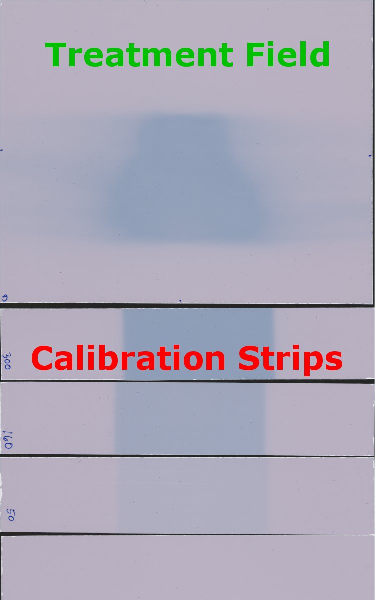
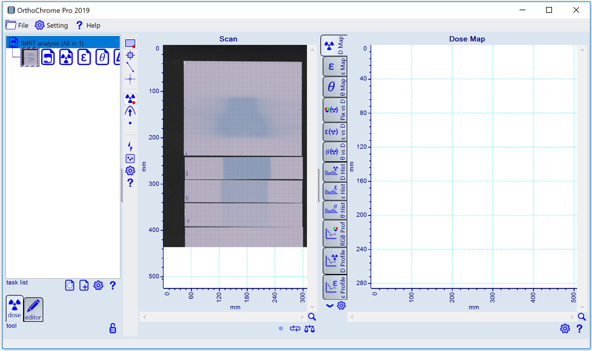
 icon ('Landscape scan') and load bitmap 'Scan_Prostate 250 cGy Strips.tif'.
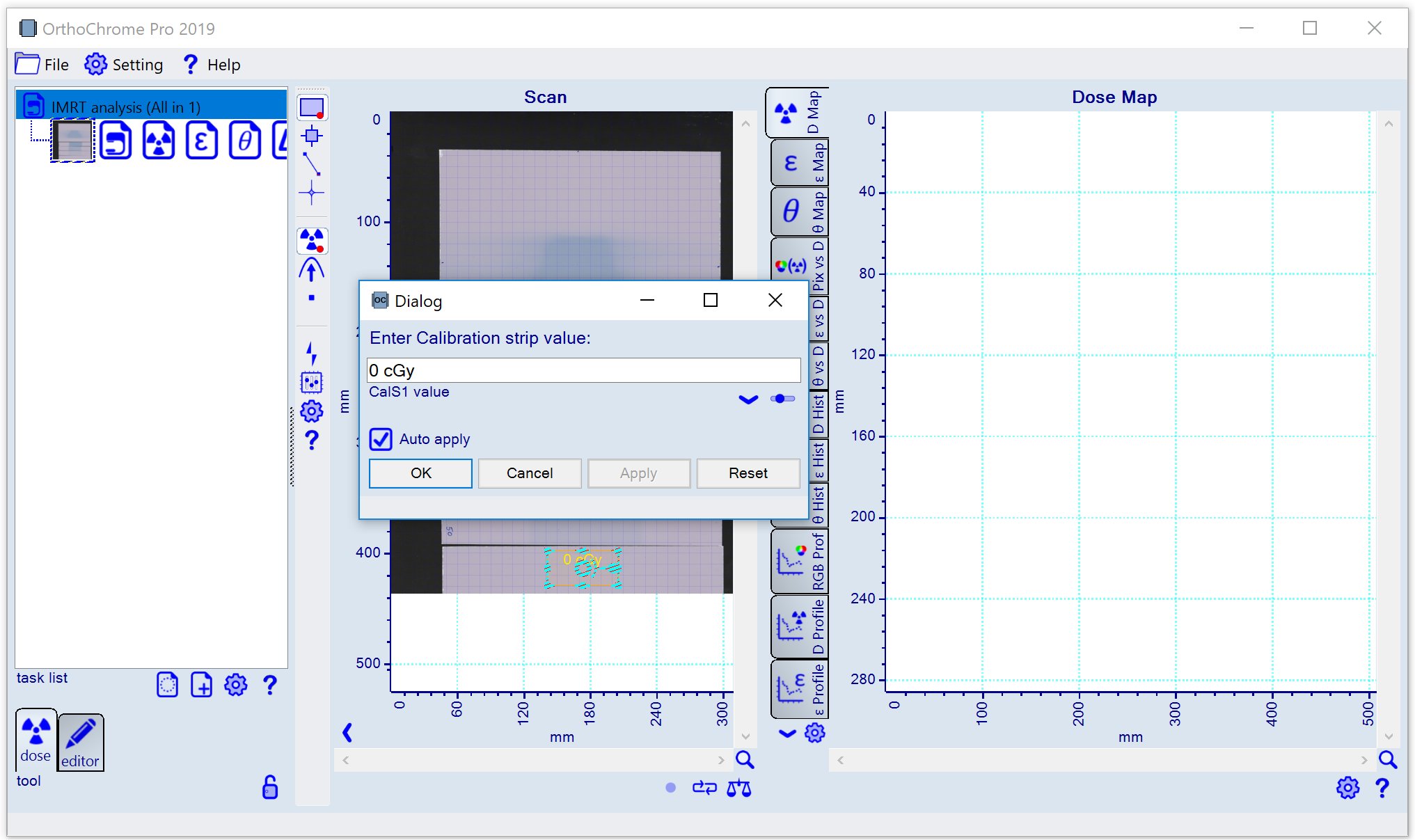
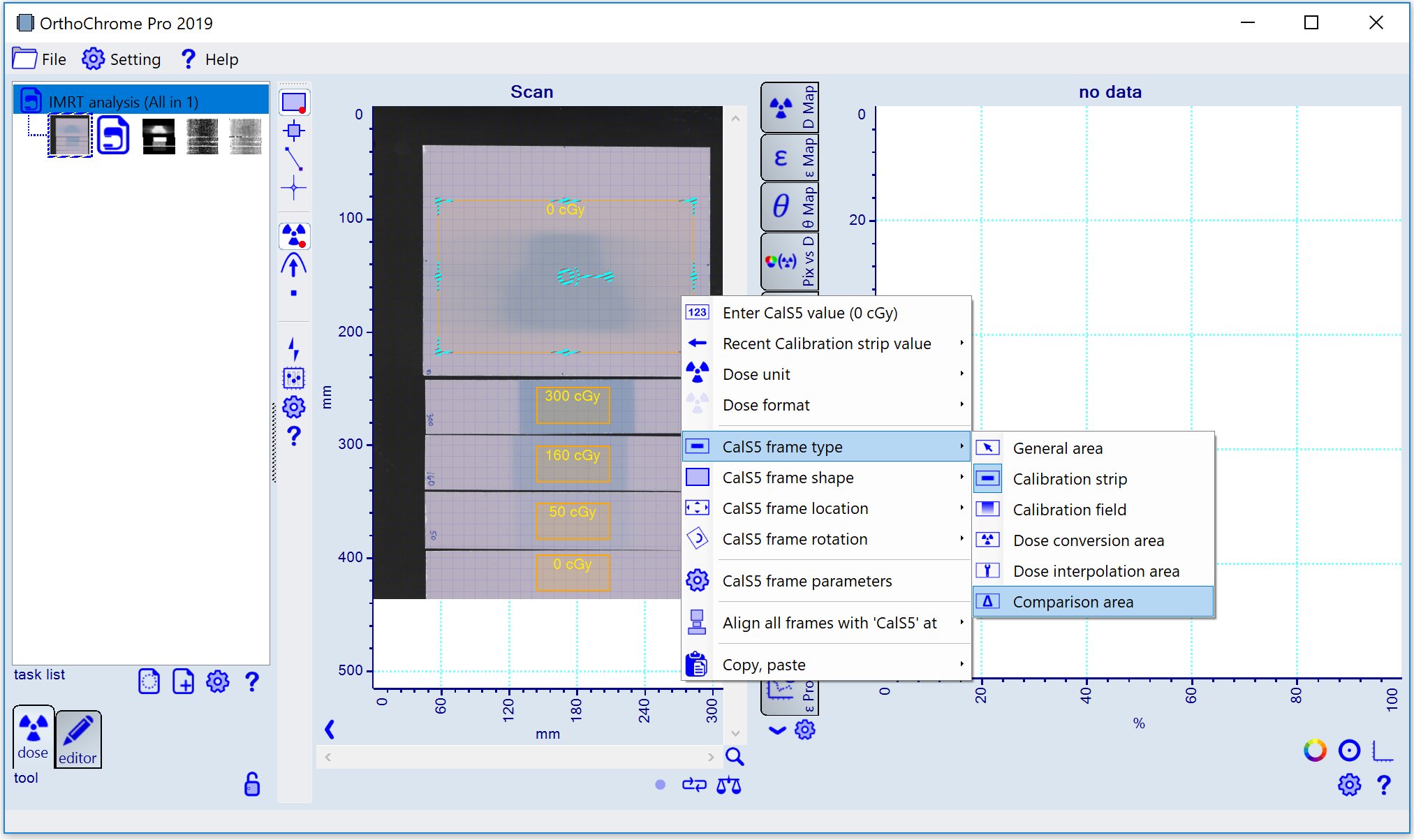
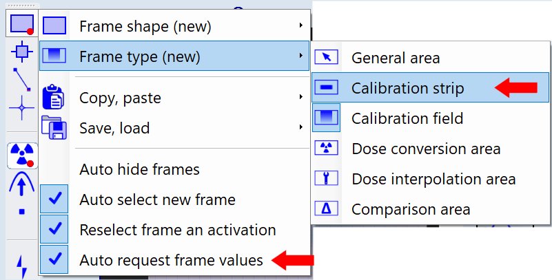 and draw frame for film strip to marke the calibration area. When the frame is selected a dialog panel to input the calibration dose value as shown below.
Note: The input of each dose value has to be fishshed by pressing the 'Enter' key.
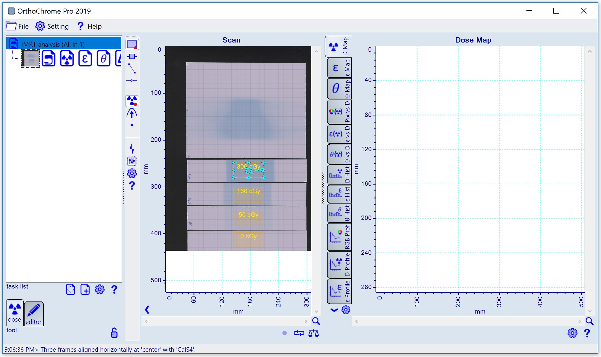
 button. The running process is indicated by red LED symbol
 underneath the center image.
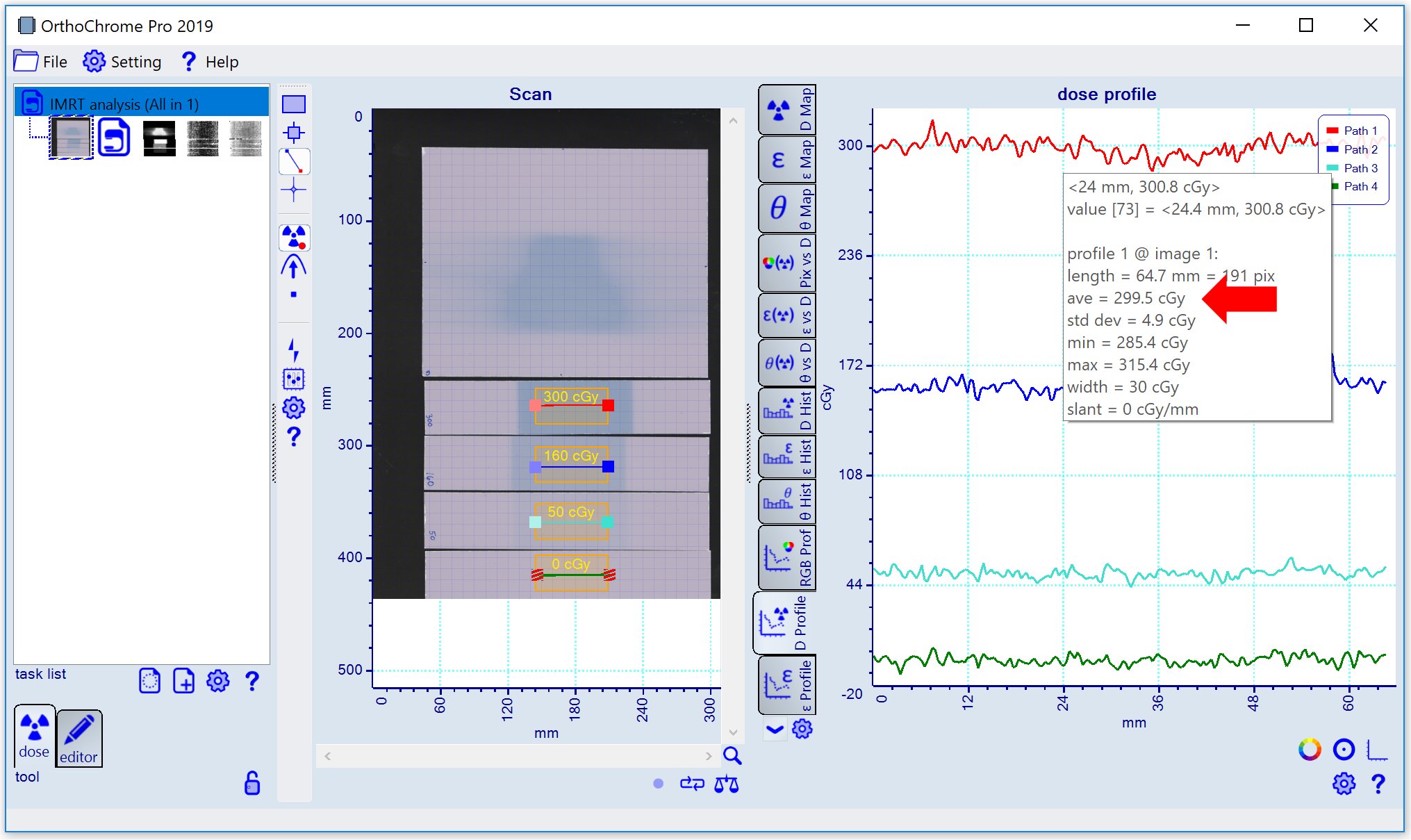
To profile the calibration data assign a paths for each calibration frame as shown below.
Select the 'Dose Profile' tab
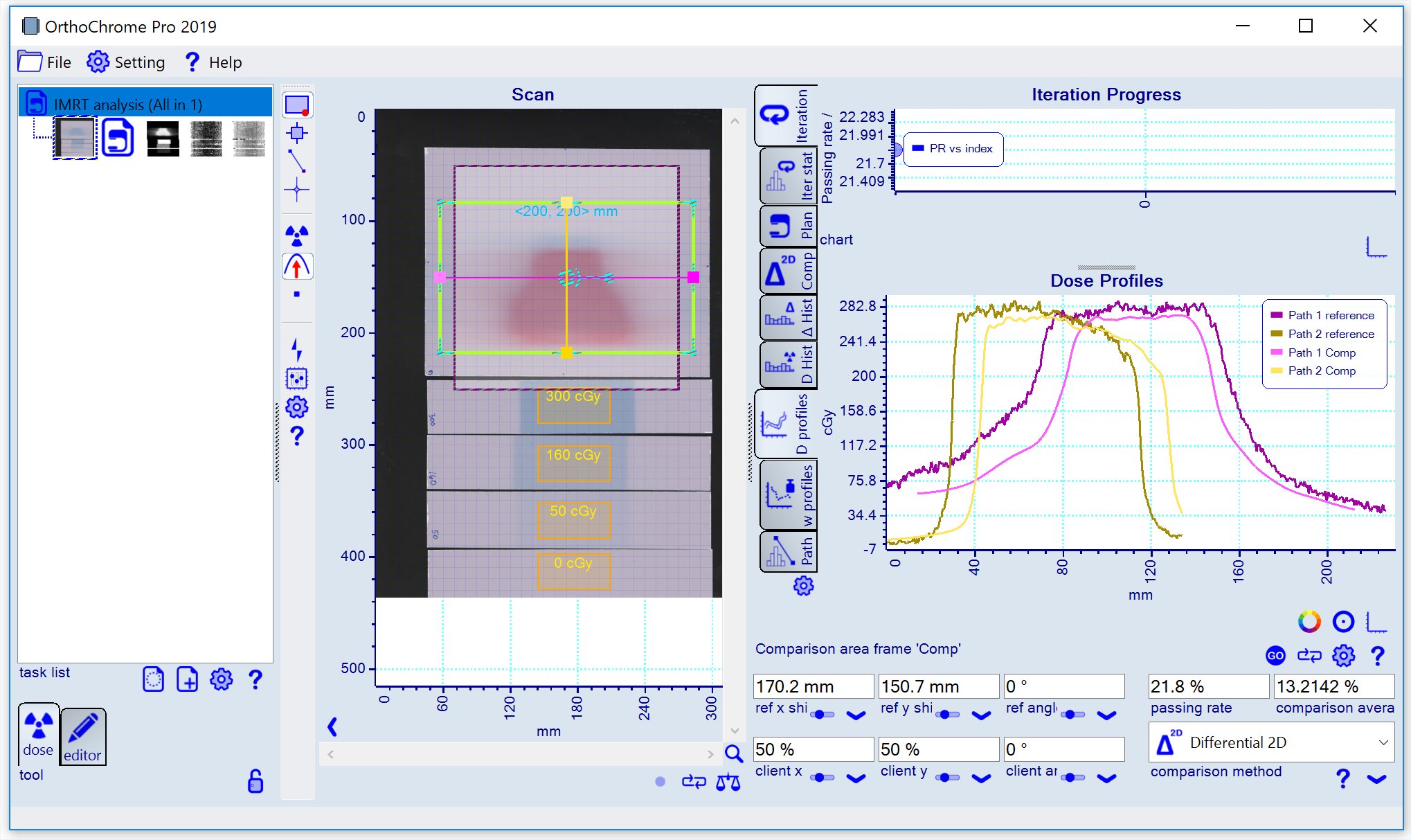
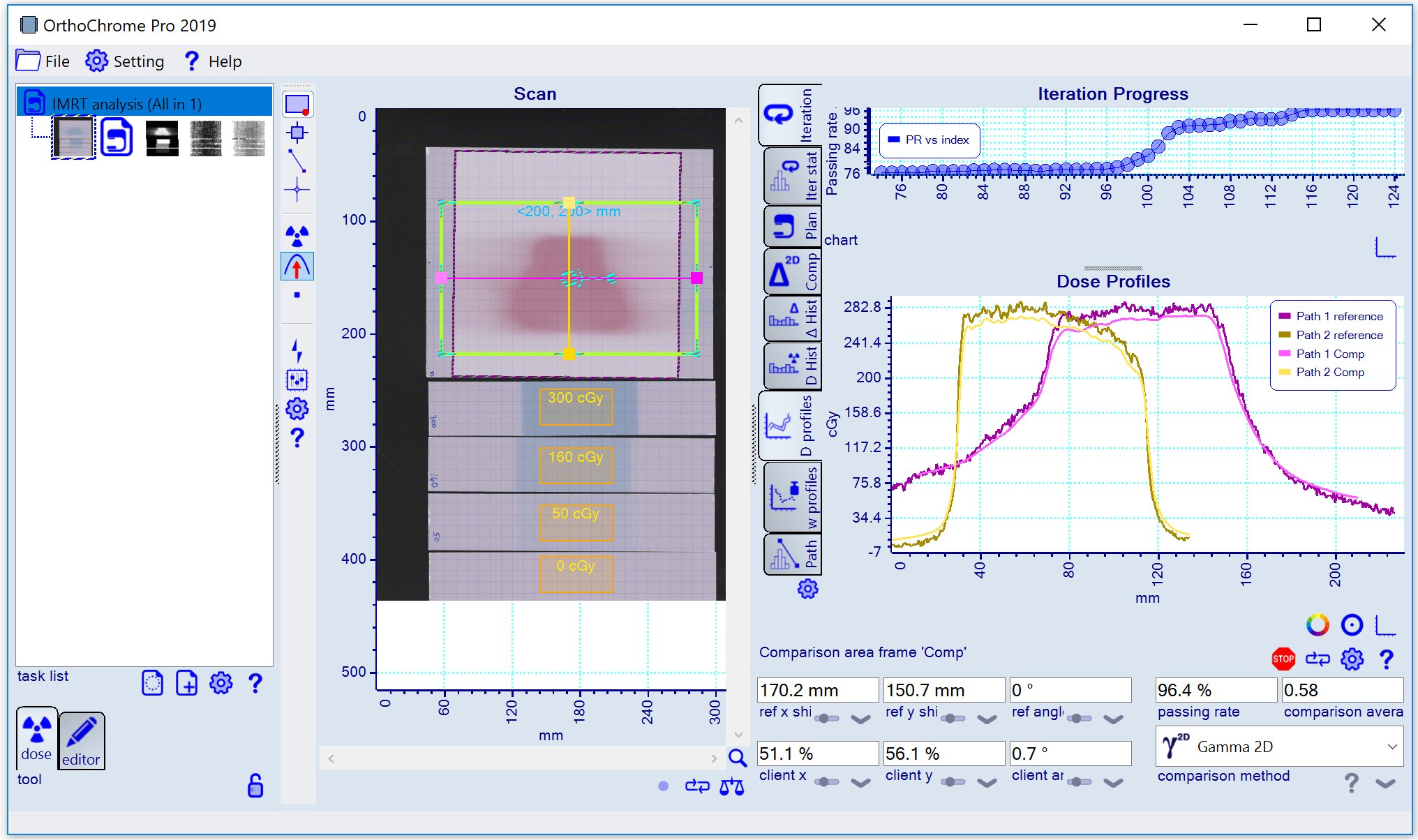
 of the chart mosaic to get the display as shown below indicating that the registration of the calibration plan is not perfect yet.
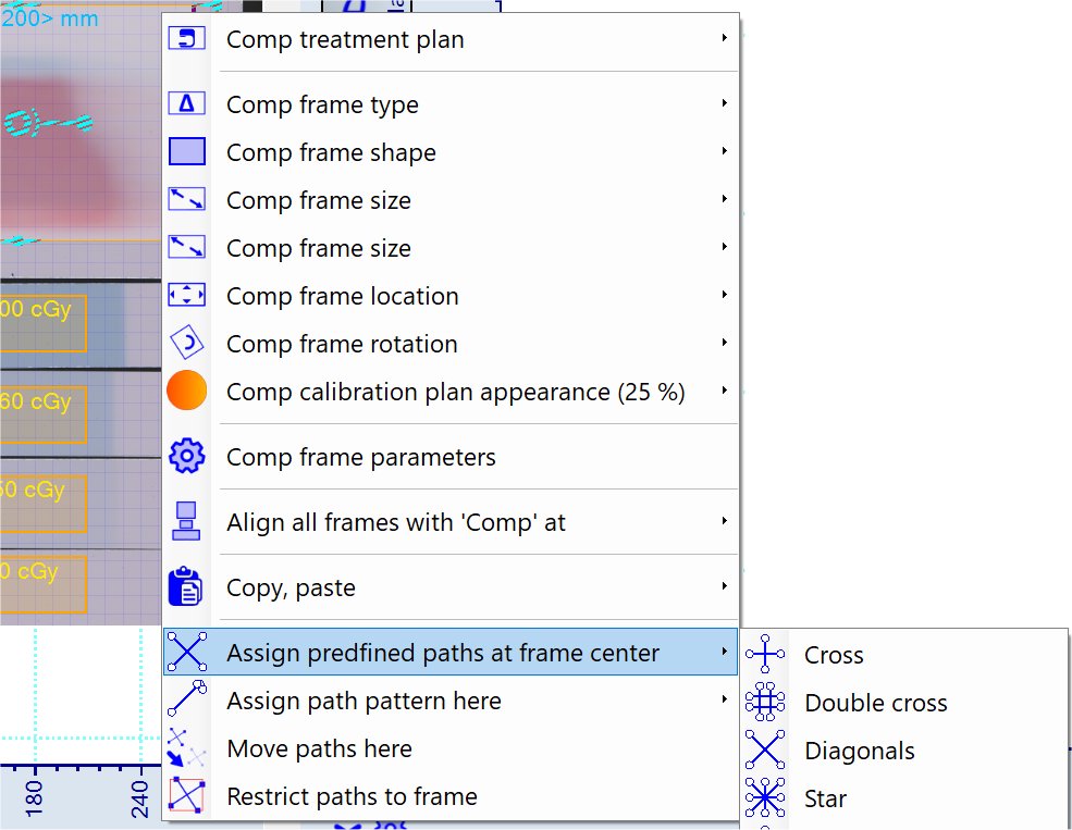
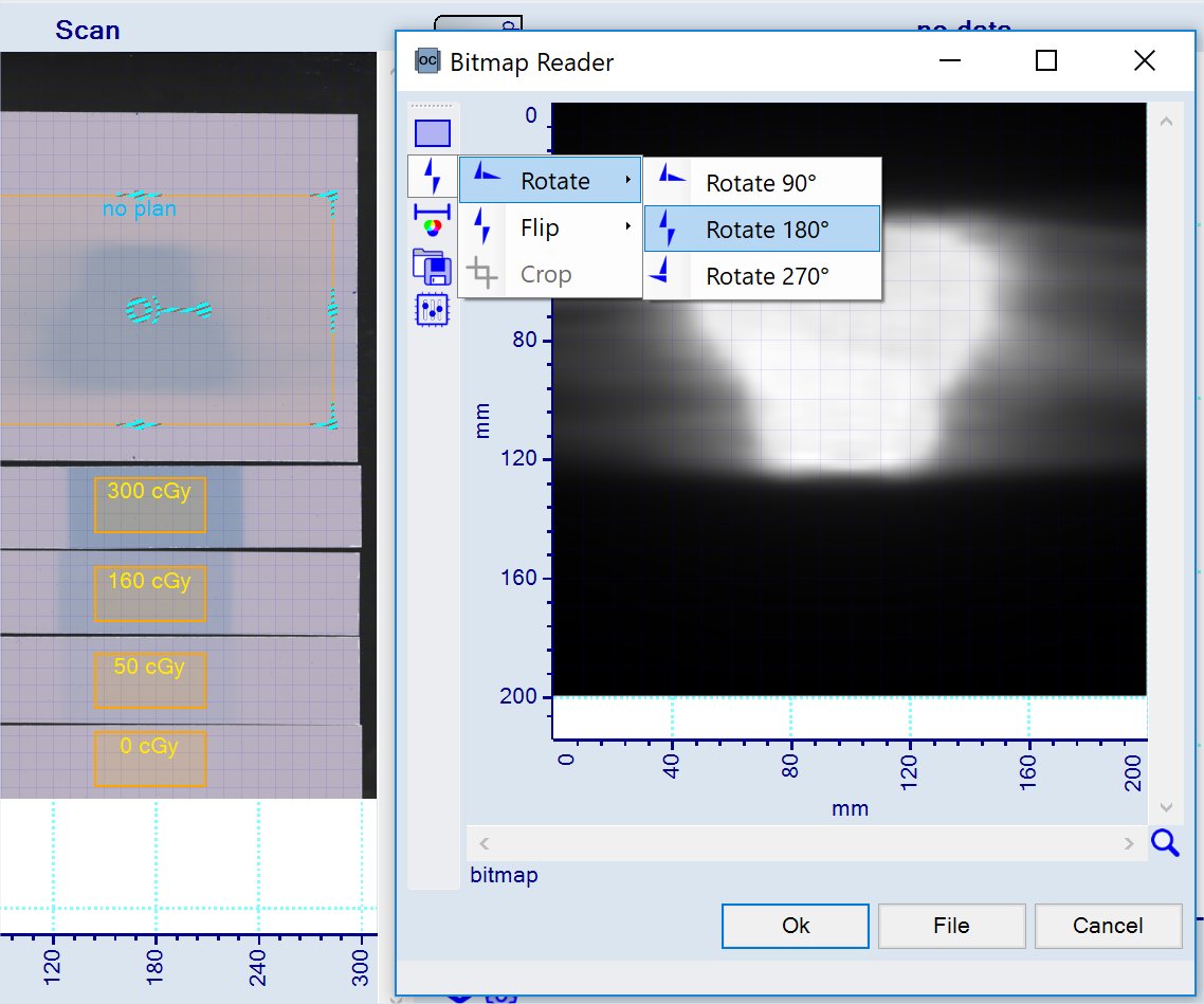 Assign path pattern to comparison frame to profile dose vs plan data, use context menu as shown below.
 Toggle from calibration mode
